Ever heard of PostmarketOS? If not, then here's a short summary: PostmarketOS aims to bring "[a] real Linux distribution for phones and other mobile devices [...]" to, well, phones and other mobile devices.
Ever since reading about it, I've been intrigued by the idea of running a real Linux distro with my UI of choice, be it Plasma or Unity, on my phone. Perhaps even running the device without any proprietary firmware blobs. So, I tried my best at contributing to PostmarketOS, which resulted in 3 MRs that have been accepted into master (Sorry for forgetting to bump the pkgver...).
With this series - if I manage to not break my phone - I want to document what I, someone who has absolutely no idea what he is doing, learned about all this stuff, how I went about it and what the results are.
Mainline Hero #0 - Preparations
Before I can even think about trying to make mainline Linux run on my Galaxy S7, we should think
about how we can diagnose any issues that the kernel or the bootloader might have. And how do
professionals debug? Exactly! With a lot of printf() statements. But how can we retrieve those
from the device?
Getting Output
While preparing myself for this task, I learned that there are a couple of ways.
One is called RAM console. What it does is just dump everything that the kernel prints into a
reserved region of memory, which can later be retrieved by reading from /proc/last_kmsg with a
downstream kernel.
The other one is via a serial cable. This sounded pretty difficult at first, the reason being that I have no idea about hardware, besides the occasional PC hardware talk. I imagined a cable coming out of a box, packed to the brim with electronics doing some black magic.
The reality is - thankfully - much simpler. It is, basically, just a normal USB cable. I mean: USB literally stands for Universal Serial Bus. But how come my PC does not read those kernel logs when I plug in my phone?
As it turns out, there is a component built into my phone which decides exactly what data flows from my phone to the PC. Reading the XDA post which the PostmarketOS Wiki linked helped understand that my device contains a MUIC, a chip which multiplexes the data lines of the USB cable towards different "subsystems". As I later learned, the USB standard for connectors of type Micro Type B requires 5 pins: power, ground, RX, TX and ID. Power and ground should be self-explanatory if you know anything about electronics (I don't). RX and TX are the two data lines that USB uses. As USB is just a serial connection, only one line is used for sending and one for receiving data. The ID line is the interesting one: it tells the MUIC what subsystem it should multiplex the data lines to.
Pinout diagram of the Micro Type B connector:
  _______________
 /               \
|  1  2  3  4  5  |
+--|--|--|--|--|--+
   |  |  |  |  +-o Ground
   |  |  |  +----o ID
   |  |  +-------o D+ (Data)
   |  +----------o D- (Data)
   +-------------o VCC (Power)
According to the XDA post, the MUIC switches to serial - used for dumping output of the bootloader and the kernel - if it measures a resistance of 619kOhm attached to the ID pin. So, according to the diagram in the post, I built a serial cable.
But how did the author of the XDA post know of the exact resistance that would tell the MUIC to switch to
serial? If you grep the
S7's defconfig,
for MUIC, then one of the results is the KConfig flag CONFIG_MUIC_UNIVERSAL_MAX77854.
If we then search the kernel tree for the keyword max77854, we find multiple files; one being
drivers/mfd/max77854.c. This file's copyright header tells us that we deal with a Maxim 77854 chip. Judging
from the different files we find, it seems as if this chip is not only responsible for switching between serial
and regular USB, but also for e.g. charging (drivers/battery_v2/include/charger/max77854_charger.h).
However, the really interesting file is drivers/muic/max77854.c, since there we can find an array of structs
that contain strings. Sounds pretty normal until you look at the strings more closely: One of the strings is
the value "Jig UART On":
[...]
#if defined(CONFIG_SEC_FACTORY)
	{
		.adc1k		= 0x00,
		.adcerr		= 0x00,
		.adc		= ADC_JIG_UART_ON,
		.vbvolt		= VB_LOW,
		.chgdetrun	= CHGDETRUN_FALSE,
		.chgtyp		= CHGTYP_NO_VOLTAGE,
		.control1	= CTRL1_UART,
		.vps_name	= "Jig UART On",
		.attached_dev	= ATTACHED_DEV_JIG_UART_ON_MUIC,
	},
#endif /* CONFIG_SEC_FACTORY */
[...]
The keyword ADC_JIG_UART_ON seems especially interesting. Why? Well, the driver has to know what to do
with each measured resistance. It would make sense that we call the constant which contains the resistance
something like that. Additionally, it is the only constant name that does not immediately hint at its
value or function.
So we search the kernel source for this keyword. Most occurences are just
drivers using this constant. But one hit shows its definition: include/linux/muic/muic.h. There we
find on line 106
a comment which states that this constant represents a resistance of 619kOhm.
To actually build the serial cable, we need to have a USB Type B male connector that we can solder our cables to. My first thought was to buy a simple and cheap USB Type B cable, cut it, remove the isolation and solder my connectors to it. I, however, failed to notice that the Type A part of the cable - the one you plug into e.g. your PC - only has 4 pins, while the Type B part has 5. After stumbling upon some random diagram, I learned that for regular USB connectivity, such as connecting your phone to your PC, the ID pin is not needed, so it is left disconnected. As this plan failed, I proceeded to buy a USB Type B male connector. Since I bought it on the Internet and the seller did not provide a diagram of what pad on the connector connects to what pin, I also ordered a USB Type B female breakout board.
After all parts arrived, I used a digital multimeter to measure the resistance between each pad on the connector and on the breakout board. Since I have no idea about electronics, let me explain: Resistance is defined as $R = \frac{U}{I}$, where $R$ is the resistance, $U$ the voltage and $I$ the current. This means that we should measure - practically speaking - infinite resistance when no current is flowing and some resistance $R \gt 0$ when we have a flowing current, meaning that we can test for continuity by attempting to measure resistance.
After some poking around, I got the following diagram:
     +---------o VCC
     |   +-----o D+
     |   |   +-o GND
  ___|___|___|___
 /   ?   ?   ?   \
|      ?   ?      |
+------|---|------+
       |   +---o ID
       +-------o D-
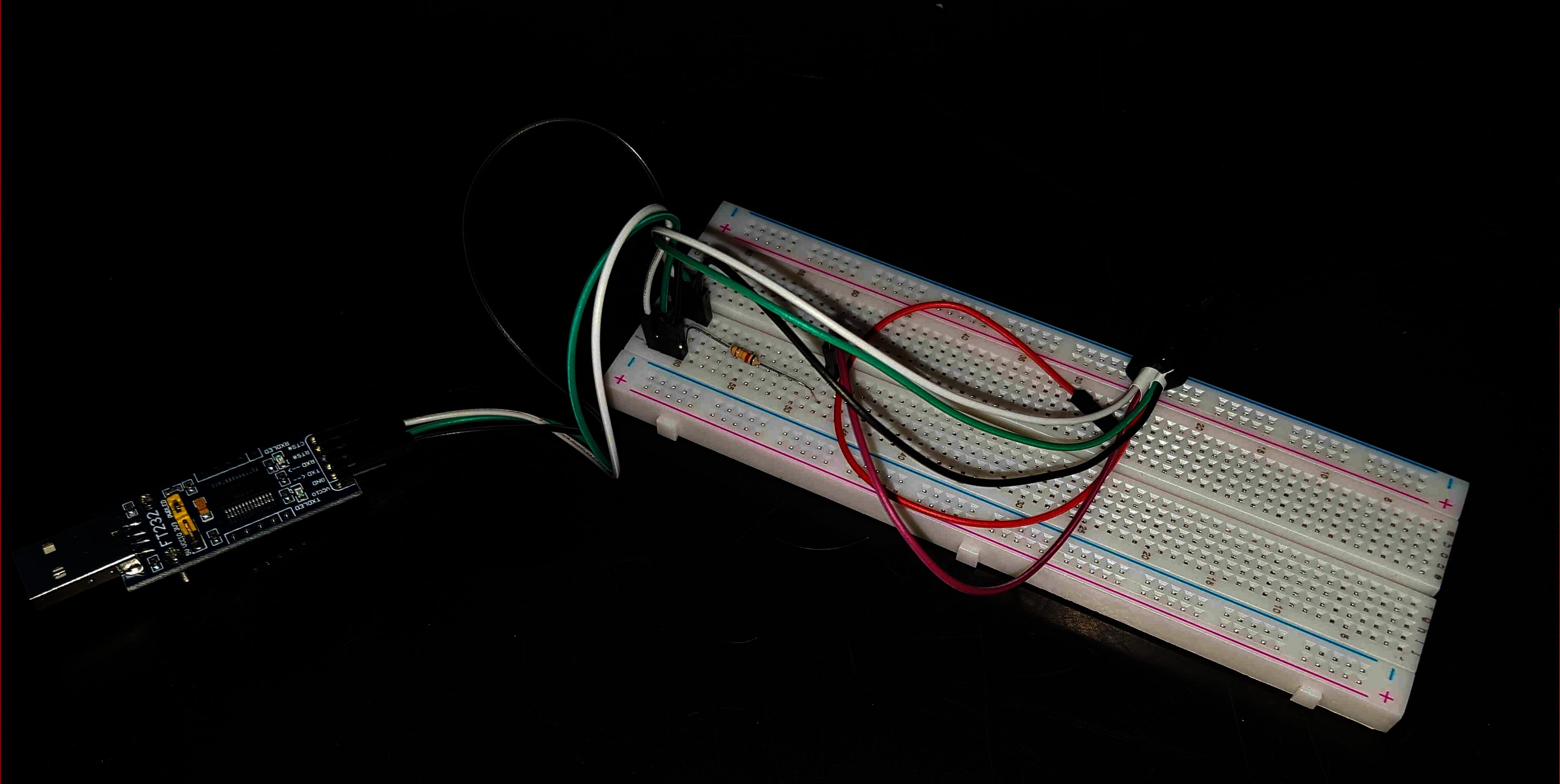
Since the data that the serial port inside the phone is coming in using a certain protocol, which also includes timing, bit order and error correcting codes, we need something to convert this data into something that is usable on the host. Since the USB specification for data may differ from what we actually receive, we can't just connect the phone's D- and D+ lines to the host USB's D- and D+. Hence the need for a device which does this conversion for us and also deals with the timing of the data: The tiny board to which all cables lead to basically just contains an FT232RL chip from FTDI. It is what does all the conversion and timing magic.
Since I don't want to accidentally brick by phone by frying it with 3.3V or 5V - though I think that damaging the hardware with 5V is pretty difficult - I did not connect the USB's 5V to the FT232's VCC port.
Booting up the device, we start to see data being sent via serial!
[...]
CP Mailbox Debug
0x10540180 : 0xdca7b414 0x 804f99f
0x10540184 : 0xdeb36080 0x8112566f
0x10540188 : 0xf4bf0800 0x2534862d
0x1054018C : 0x61ff350e 0x1208fd27
0x10540190 : 0x17e60624 0x18121baf
0x105C0038 : 0x3bd58404 0x5674fb39
CP BL flow
0x10920014 : 0x79dab841 0x9b01b3fd
0x10800028 : 0xffbd34b1 0x9fd118cc
Resume el3 flow
EL3_VAL : 0xdcfee785 0xfbb6b0a2 0xccf99641
muic_register_max77854_apis
muic_is_max77854 chip_id:0x54 muic_id:0xb5 -> matched.
[MUIC] print_init_regs
 INT:01 00 00 ST:1d 00 00 IM:00 00 00 CDET:2d 0c CTRL:1b 3b 09 b2 HVCT:00 00 LDO0:47

MUIC rev = MAX77854(181)
init_multi_microusb_ic Active MUIC 0xb5
[...]
Nice! We can see what SBOOT, the bootloader that Samsung uses, tells us. But for some reason, I wasn't
able to get into the SBOOT prompt to tell the kernel to dump everything via serial. While the XDA post
used the programm minicom, which I could use to get SBOOT output, it never seemed to send the carriage
returns while I was pressing the return key like crazy. So what I did was try to use a different tool to
interact with the serial converter: picocom. And it worked!
Although I set the kernel parameters to output to the TTY device ttySAC4, just like the XDA post said,
I did not receive any data.
Device Tree
So we can just try and boot mainline on the phone then, yes? With a very high probability: no. The reason being that the kernel has no idea about the actual hardware inside the phone.
This may seem weird as you don't have to tell your kernel about your shiny new GPU or about your RAM. The reason is that your PC is designed to be modular: You can swap the CPU, the RAM and even the attached devices, like your GPU. This means that on X86, the CPU is able to discover its hardware since there is only one bus for attaching devices (ignoring RAM and the CPU): the PCI bus. How does the CPU know about its RAM? The RAM-modules are swappable, which means that the CPU cannot anticipate just how much RAM you have in your system. These information get relayed, perhaps via the MMU, to the CPU.
Can't we just probe the available memory in an ARM SoC? Technically yes, but it would take a lot of time if we have a modern 64 bit CPU. Moreover, how do you know that a probed memory location is not a memory mapped device? Wouldn't it make sense to bake this data into the SoC then? Here again: not really. The reason is that the SoCs are vendor specific. This means that the vendor basically just buys the rights to put the CPU into their SoC. The rest is up to the vendor. They can add as much RAM as they want, without the CPU designer having much input. This means that the data must not be hardcoded into the CPU.
On ARM and probably most other microprocessors devices can be memory mapped, which means that they respond to a certain region of memory being written to or read from. This makes auto-discovering devices quite difficult as you would have to probe a lot of memory regions.
As an example: Imagine we can access 4 different locations in memory, each holding 1 byte of data. These regions
are at the memory addresses 0x1 to 0x4. This means that we would have to probe 4 memory locations. Easy,
right?
Not exactly. We would have to probe 4 times to discover 4 possible memory mapped areas with a width of 1 byte.
If we allow a width of 2 bytes, then we would have to probe 3 different regions: 0x1-0x2, 0x2-0x3 and
0x3-0x4.
This assumes that memory maps need to be directly next to each other. Otherwise we would need to use the
binomial coefficient.
This results in 10 (4x 1 byte, 3x 2 bytes, 2x 3 bytes and 1x 4 bytes) different probing attempts to discover possible memory mapped devices. This does not seem much when we only have a 2 bit CPU, but in the case of the S7, we have a 64 bit CPU; so we would have to probe about $\sum_{n=1}^{2^{64}} n$ times. This finite sum is equal (German Wikipedia) to $\frac{1}{2} 2^{64} {(2^{64} + 1)} = 1.7014 \cdot 10^{38}$. Quite a lot! Keep in mind that this calculation does not factor in any other busses that the SoC might use; they can, probably, use their own address space.
So, long story short: We need to tell the kernel about all the hardware beforehand. This is where the so-called
Device Tree comes into play. It is a structured way of describing the attached hardware. You can find examples
in the kernel tree under arch/arm{,64}/boot/dts/. The problem that arises for my phone is that it
uses the Exynos SoC from Samsung. While Exynos 7 or older would just require an addition to the already existing
Device Tree files, the S7 uses the Exynos 8890 SoC. This one is not in mainline, which mean that it is
required to port it from the downstream kernel into mainline.
Device Support
The challenge that follows, provided I don't brick my phone, is the kernel support for the SoC's hardware.
GPU
The GPU of the Exynos 8890 SoC is a Mali-T880 from ARM. While there is no "official" FOSS-driver for it, one is in development: Panfrost. One of the developers once mentioned in PostmarketOS' Matrix channel that the driver is not ready for day-to-day use. But hopefully it will be in the forseeable future.
Wifi
While I found no data on the Exynos 8890's Wifi-chip, I managed to allow the downstream kernel to use it, albeit with its proprietary firmware (MR).
This patch requires a patch which changes the path of the firmware in the file drivers/net/wireless/bcmdhd4359/dhd.h.
The license header of said file
hints at a chip from Broadcom. The model of the chip appears to be 4359. What the dhd stand for? I don't know.
Looking at the compatibility of the kernel modules for Broadcom wireless chips, we can find that the BCM4359 chip is compatible. But is that the same as the module folder's name specifies? Again, I don't know. Hopefully it is...
Other Components
At the time of writing this post, it has been a "long time" since I last flashed PostmarketOS on my phone to look at what the kernel is saying. All of this device data I gathered by looking at spec sheets by Samsung or the kernel. So I don't really know what other hardware is inside my S7.
Next Steps
The next steps are actually testing things out and playing around with values and settings and all kinds of things.
Other Devices I Have Lying Around
This may be off-topic for the "Mainline Hero" series but I recently tried to find out whether another device I have lying around - a Samsung Galaxy Note 8.0 - also uses such a MUIC to multiplex its USB port. While at first I somehow found out, which I now know is wrong, that the Note 8.0 uses the same Maxim 77854 as my S7, I discovered that the Note 8.0 does use a MUIC, just not the 77854. Since I found no other links talking about this, I am not sure until I test it, but what I will do is tell you about how I reached this conclusion!
If you grep the defconfig for the herolte for
"77854", then one of the results is the flag CONFIG_MUIC_UNIVERSAL_MAX77854. The prefix CONFIG_MUIC makes
sense since this enables kernel support for the Maxim 77854 MUIC. As such, we should be able to find
an enabled MUIC in the Note 8.0's defconfig.
If we grep for CONFIG_MUIC, then we indeed get results. While the results do not look like the one for
the 77854, we get ones like CONFIG_MUIC_MAX77693_SUPPORT_OTG_AUDIO_DOCK. This indicates that the Note 8.0
has a Maxim 77693 MUIC built in. But it's not a very strong indicator. Since the kernel source is available
on Github, we can just search the repo for the keyword "MAX77693". One of the results hints at the file
drivers/misc/max77693-muic.c. Looking at the Makefile of the drivers/misc directory, we find that this
source file is only compiled with the KConfig flag CONFIG_MFD_MAX77693. Grepping the Note 8.0's defconfig
for this flag yields the result that this kernel module is enabled, hence hinting at the existence of a MUIC
in the Note 8.0.
If we take a closer look at the source file at drivers/misc/max77693-muic.c, we can find an interesting part
at line 102:
[...]
  ADC_JIG_UART_ON		= 0x1d, /* 0x11101 619K ohm */
[...]
This means that, as the Maxim 77854 requires a 619kOhm resistor to enable UART, we can debug the Note 8.0 with the same serial cable as the S7.
Plugging it into the DIY serial cable and booting it up, we also get some output:
[...]
BUCK1OUT(vdd_mif) = 0x05
BUCK3DVS1(vdd_int) = 0x20
cardtype: 0x00000007
SB_MMC_HS_52MHZ_1_8V_3V_IO
mmc->card_caps: 0x00000311
mmc->host_caps: 0x00000311
[mmc] capacity = 30777344
Theory proven! We can also serial debug the Note 8.0 using the same cable.
Some Closing Words
I want to emphasize that just very few of the things I mentioned were discovered or implemented by me. I just collected all these information to tell you about what I learned. The only thing that I can truly say I discovered is the MR for the Wifi firmware...
Additionally, I want to make it clear that I have no idea about microelectronics, electronics or ARM in general. All the things I wrote that are about ARM or electronic - especially everything in the Device Tree section - is pure speculation on my side. I never really looked into these things, but all the statements I made make sense to me. You can't just probe $2^{64}$ different memory addresses just to figure out how much RAM you have, can you?